2.4.2 Analysis of cantilever motion (perturbation theory)
Consider one of the solution methods to the probe's tip equation of motion in an arbitrary potential
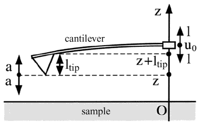
 (see formula (1) in chapter 2.4.1). Assume the tip of length
  is attached to the cantilever end as depicted in Fig. 1.

Fig. 1. Problem formulation.
If the free cantilever beam end is excited and oscillates with amplitude
 and frequency
 at some height
 above a sample surface, i.e.
 , the tip equation of motion is given by

(1)
where
 – cantilever effective mass,
 – Q-factor,
 – cantilever stiffness (see (10) in chapter 2.1.2),
 – cantilever resonant frequency,
 – probe-sample interaction potential,
 – probe-sample distance.
From condition
 one can easily determine the tip equilibrium position which is a certain function of
 . Upon changing the variables
 and
and
 , the equation of motion is transformed to the following

(2)
where
 and
and
 . As the cantilever natural frequency is
 , equation (2) can be written as:

(3)
Introducing a new parameters designation, equation (3) takes the following form:

(4)
where


(5)
and
 – some small parameter (
 ).
).
Solution of equation (4) for the case
 and
and
 can be obtained with the help of Krilov-Bogolyubov-Mitropolsky (KBM) method [1] which is a kind of perturbation theory.
If the solution of (4) is supposed to differ slightly from that for the harmonic oscillator, i.e.
 with
with
 and
and
 , the functions
 and
and
 must meet the following conditions (to within the first order terms
 ):
):


(6)
where we introduced the auxiliary function
 determined by the probe-sample interaction potential:

(7)
For the certain class of equation (4) solutions, the cantilever end's motion is a simple harmonic motion with fixed values of  and
and
 . These fixed values are the critical points of equations (8) and (9) for the case when condition
 is met. Using this condition, the following equations set can be written

(8)
Eliminating variable
 from the set (8), the oscillation amplitude dependence on the frequency, i.e. the system amplitude-frequency characteristic (AFC), can be obtained:

(9)
This relation is not explicit and can not be calculated in a general form. However, using methods of numerical solution of explicit equations, the given system AFC for the specific probe-sample interaction potential can be calculated. In [2] such a calculation was performed assuming that potential
 is the Lennard-Jones potential that is written as:

(10)
Typical system AFCs as a function of probe-sample distance are shown in Fig 2a. The same relations obtained by the numerical solution of the differential equation of motion (1), are depicted in Fig. 2b for comparison.

Fig. 2. Comparison of the tip-sample system AFC calculated using perturbation theory
and numerical integration of the motion equation [2].
As is seen from the picture, when moving away from the sample surface (reduction of the interaction potential), the AFC curves approach these of the simple harmonic oscillator. The closer the tip is to the sample, the more distorted are the resonance curves. Notice that situations are available when a few stable amplitudes determined by starting conditions correspond to one driving frequency.
From (8) one can find the phase-frequency characteristic (PFC) of the system noticing that the following is true for
 :
:

(11)
This expression unambiguously relates the phase of oscillation to the amplitude. Thus, once system AFC is calculated, the PFC can be easily obtained using (11).
Summary.
- Theoretical technique of cantilever motion equation analysis is described. This method is correct for arbitrary driving force amplitude.
- If small oscillation condition is not satisfied (probe-sample interaction force varies very abruptly during oscillations amplitude), it is possible to exist several stable solution (state). The state choice depends on initial conditions at given driving frequency.
- Resonance characteristics of probe-sample system is given (9, 11) at arbitrary interaction potential
 .
.
References.
- N. Bogolyubov and Y.A. Mitropolsky, Asymptotic Methods in the Theory of Nonlinear Oscillations. Gordan and Breach, New York, 1961.
- N. Sasaki and M. Tsukada, Appl.Surf.Sci. 140 (1999) 339-343.


